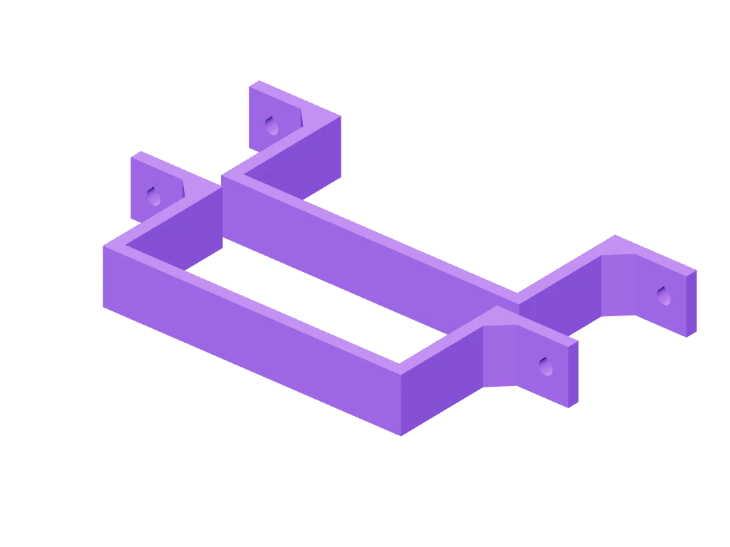
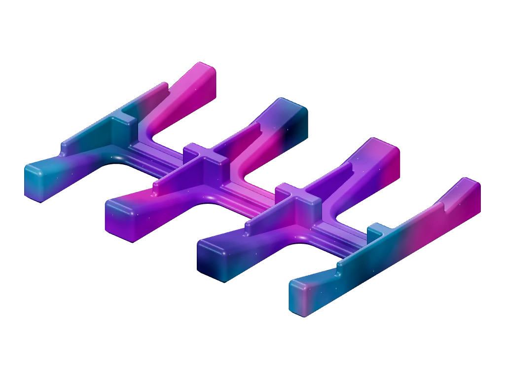
Custom electronics mounting saddles
One measured PETG saddle pair for an enclosed device beneath a flat surface. Separate screw spacings and sideways offsets reuse unusual existing hole positions.
From $16.00Customizable
Loading 3D preview…
Bambu A1 · Fits the 256 mm bed
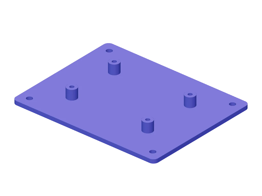
Print the broad plate bottom down, supports pointing up. PETG, 100% infill, 0.4 mm nozzle; vertical bores and 45-degree underside seat roofs need no supports. The store reserves an 11 mm bed margin.
One plate only; hardware separate. Assemble the board with 90-degree flat-head bolts from below, washers and nuts above while both faces are accessible, then fasten the complete assembly to the enclosure. Check flush bolt heads, component/connector clearance and enclosure lid height. Indoor low-voltage hobby boards only; physical print and fit testing are pending.
Match measured circuit-board holes to a different enclosure pattern. One PETG plate with raised supports, independent screw centers and recessed underside bolts.
Example measurements only. Check both patterns and the enclosure's usable floor space.
Match two different mounting patterns
Look down at the component side of the board in its installed position. X goes right and Y goes up. Board-hole centers use the board’s bottom-left corner; enclosure-hole centers use the plate’s bottom-left corner. Pair the X and Y lists in order. Mirror any tracing taken from below.
Dashed board and screw-access envelopes are measurement guides. The board and hardware are separate.
Finished plate: 120 × 95 × 3.2 mm. Board underside: 8 mm above the plate; remaining component gap: 4 mm. Complete print height: 11.2 mm.
| Hole | Local X | Local Y | Plate X | Plate Y |
|---|---|---|---|---|
| B1 | 4 | 4 | 28 | 26.5 |
| B2 | 68 | 4 | 92 | 26.5 |
| B3 | 68 | 46 | 92 | 68.5 |
| B4 | 4 | 46 | 28 | 68.5 |
| E1 | 8 | 8 | 8 | 8 |
| E2 | 112 | 8 | 112 | 8 |
| E3 | 112 | 87 | 112 | 87 |
| E4 | 8 | 87 | 8 | 87 |
Board bolts: 3.2 mm clearance, 6.2 mm head seats with 1.5018 mm depth and a 90° included angle. Support tops are 8 mm across. Enclosure bores: 4.5 mm; head/washer envelope: 9 mm.
Measure the usable flat enclosure floor and enter the finished plate size with fit clearance already allowed. The plate needs support beneath it. Two to six board holes and two to six enclosure holes are independent; they do not need equal counts. Presets are examples, with no named-board or enclosure fit claim.
Use 90° flat-head machine bolts through the plate from below, washers and nuts above the board, and pan-head screws for the enclosure. Assemble the board, bolts, washers and nuts while you can hold each bolt head from below; then fasten the complete assembly using the accessible enclosure holes. Check the actual head fits flush and cannot protrude into the enclosure floor. Bolt length must cover the full plate/support height, board thickness, washers, nut and required thread engagement. Check the case screws against its existing bosses. Hardware is not included.
Each printed support must touch a component-free mounting area on the board underside. Check all copper, solder, components, connectors, overhanging cables and the complete board/washer/nut height against the enclosure lid. The component-drop measurement reserves at least 2 mm above the plate; it cannot check individual component positions. Enclosure screws must remain accessible outside the board footprint. A solid plate reduces airflow below the board.
Indoor low-voltage hobby circuits only. No mains, hot power electronics, outdoor/sealed, electrical, fire or load rating. Physical print and fit testing are pending. Standard standoffs, stock adapters or drilled sheet can cost less when both patterns fit.
Match a small circuit board to an existing enclosure with a different screw pattern. Enter independent board and enclosure hole centers, board placement and underside clearance. One PETG plate with raised supports and recessed underside bolt seats per quantity. Bolts, nuts, washers, board and enclosure are separate. Indoor low-voltage hobby electronics only. Physical print and fit testing are pending; no brand compatibility, load, thermal, electrical or fire rating. View from the board's component side in its installed position: X right and Y up. Board centers are measured from the board bottom-left corner; enclosure centers are measured from the plate bottom-left corner. Enter the board's placement on the plate separately. Pair X and Y lists in order, with two to six holes in each independent pattern. Mirror any tracing taken from below. Enter the finished plate size with enclosure clearance already allowed; the plate needs a flat supporting surface or sound existing mounting bosses. Measure the largest component or solder projection below the board; at least 2 mm remains above the plate. Each support must touch a component-free mounting area. Check copper, connectors, cables, washers, nuts and complete board height against the enclosure and lid separately. The solid plate reduces underside airflow. Assemble the board with 90-degree flat-head machine bolts from below, washers and nuts above while both faces remain accessible so you can hold each bolt head. Then fasten the complete assembly through the accessible enclosure holes using pan-head screws in its existing bosses. Hardware is separate. Check actual bolt heads sit flush; their selected head diameter forms 90-degree underside seats. Board-bolt length must cover full plate/support height, board thickness, washers, nut and thread engagement. The enclosure screws remain outside the board footprint for access. Presets are examples, with no named-board or enclosure compatibility. No printed threads, captive nuts or inserts are needed. Print broad plate bottom down, supports up, PETG at 100% infill with a 0.4 mm nozzle, without supports. Vertical bores and 45-degree underside seat roofs are included in the same browser solid and STL. The complete part must fit the 245 mm usable envelope inside the Bambu A1's 256 mm bed; check an added brim separately. Exact polygon material volume and surface pricing includes every support, bore and countersink; checkout validates and recalculates. Indoor low-voltage hobby boards only; no mains, hot power electronics, outdoor/sealed use or protective-barrier replacement. No load, thermal, electrical or fire rating. Physical print and fit testing are pending. Stock standoffs, adapters or drilled sheet can cost less when suitable. Original geometry; no third-party CAD or mesh copied.
One measured PETG saddle pair for an enclosed device beneath a flat surface. Separate screw spacings and sideways offsets reuse unusual existing hole positions.
From $16.00Customizable
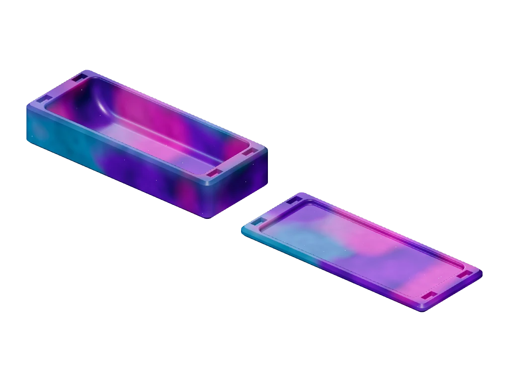
A box and lid for keeping dice together and rolling at the table.
From $22.00
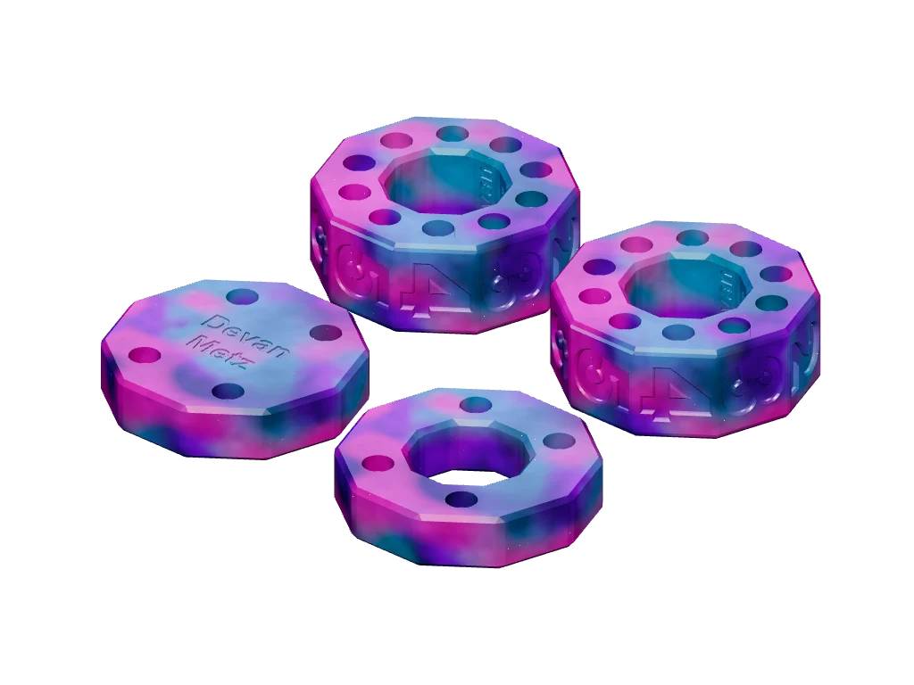
Two numbered rotary rings for tracking a two-digit game total.
From $16.00
Fit actual sleeves and the tallest loose deck stack in an inclined play tray with open finger access. Original tray remains available.
From $18.00Customizable